Gaetano, 1-to-4 antenna switch

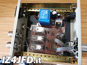
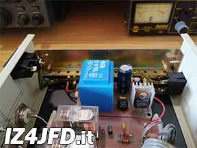
Gaetano is an active antenna switch, based on an electromechanical switching scheme with 3 relays, which implement the 4 circuit combinations that allow the RF signal to be routed from the input to one of the 4 outputs this switch is equipped with. I consider Gaetano as a kind of luxury. Until Autumn 2013, I had only one antenna - Agata, my Windom for 40/20/10 meters: after many attempts (and as much money invested in their success), I managed to install Turi, my dipole for 80 meters. Following this stroke of luck, the need to change antenna depending on the band I wanted to make a QSO on. A mechanical antenna switch? I can go for that. Designing a switching circuit would have been more fun. With all the respect, this is a very simple scheme, which is within my capabilities. The result - in fact - is Gaetano, an electromechanical antenna switch designed for those who need this optional device in their station, and for those - like me - who are "forced" to use it.
Switching stage

-

Gaetano - Switching stage
Schematic diagram (PDF)
As expected, the schematic diagram of Gaetano’s switching stage circles around the 3 Omron G2R-1 relays which "route" the RF signal. These relays have not been chosen because they are made specifically for this purpose, or for other specific reasons. Simply, they were the first SPDT (Single Pole Double Throw) relays (with 24Vdc coil) that I found when I started collecting the components I needed to make Gaetano. Once it was completed, they proved to be perfect for this role. Since each relay has two "outputs" (corresponding to the two operating states - triggered or not), it can manage two of the 4 switch outputs: in addition to the two relays needed to manage all the antennas that can be connected to Gaetano, a third relay (also the first one in the electrical diagram of the switching stage) serves to select which of the other two must be triggered (that is, which pair of output connectors is "active”). All the operating combinations for the relays and for the other components of this stage (including the LEDs placed on the front panel, each one corresponding to one output: LED 1 means output 1 is active, and so on) are selected with a 2 poles/4 positions rotary switch, which sends the bias voltage (Vgs, equal - in this case - to 5 Vdc) to the MOSfets which - based on the switching combinations - trigger the corresponding relay. Each relay needs about 20 mAdc: therefore, for the Gaetano switching stage, it is possible to use MOSfets capable of sustaining 1 Watt, or less, of DC power (at 24 Vdc drain-source voltage).


Power supply stage

-

Gaetano - Power supply stage
Schematic diagram (PDF)
The diagram of the power supply stage is the simplest application for any voltage regulator of the L78xx series, such as the L7824 used here. The 33 Vdc produced by the rectifier/filter stage are regulated at 24 Vdc by the aforementioned IC and further leveled/filtered by a second pair of capacitors (an electrolytic and a polyester one) at the output of the L7824. The only "critical" component in this diagram is the mains transformer. There are no more than 2 relays active at the same time in the Gaetano switching stage: therefore, this stage (including the other components and any possible, hidden current losses) requires a current not exceeding 50 mAdc. Consequently, it is advisable to use a transformer capable of delivering no less than this (in my case, I used a 120 mA transformer).


